

This is a survival guide to save your "buck" if you had a same problem like me in dealing with broken UTP cable on Linksys Power Over Ethernet Adapter
My actual problem is :
- the UTP cable on POE Adapter is not working to transmit data via it own UTP cable, to buy a new one it cost about $25-$60 buck(RM80 - RM200), but why spending when you can still use the POE Adapter as power supply, except for the broken UTP cable on the POE Adapter.
- the current UTP installed with Linksys WAP54GPE with RJ45 PCB Socket attached on it is not working too.


My Solution :
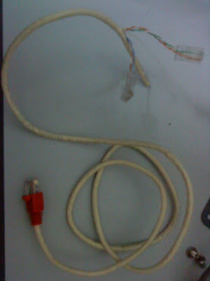
Splitting 1 UTP cable into POE connector and networking cable. At the first end of the UTP cable clamped as normal straight cable, and the second end we split it one as data cable and the other as power supply cable. So pins 1,2,3 and 6 will be connected to the switch.
See the pins out diagram


The Table
- First RJ45 Pin #Wire Color100Base-TX Signal2nd and 3rd RJ45 Pin #Wire Color100Base-TX Signal1White/OrangeTransmit+1 (2nd RJ45)White/GreenTransmit+2OrangeTransmit-2 (2nd RJ45)GreenTransmit-3White/GreenReceive+3 (2nd RJ45)White/OrangeReceive+4BlueUnused6 (2nd RJ45)BlueReceive-5White/BlueUnused4 (3rd RJ45)White/BlueBI_D3+**6GreenReceive-5 (3rd RJ45)GreenBI_D3-**7White/BrownUnused7 (3rd RJ45)White/BrownBI_D4+**8BrownUnused8 (3rd RJ45)BrownBI_D4-**
like this one


We see that the TX (transmitter) pins are connected to the corresponding RX (receiver) pins, plus to plus and minus to minus. You can also see that both the blue and brown wire pairs on pins 4, 5, 7, and 8 are not used in either standard, but actually it was used as power transmiter between the POE Adapter and WAP54GPE Access Point.
What you may not realize is that, these same pins 4, 5, 7, and 8 can be used as data or network cable as well if we going to split one UTP cable to be connected to two NIC on the same computer system such as linux pc based router/firewall, so for pins 4,5,7 and 8 are used as power supply pins.
And the result


Now the LAN connection is ON

WAP54GPE is "ON THE AIR"
hehe.. now I can browse the internet using my Sony Ericsson G705 again =P
hehe.. now I can browse the internet using my Sony Ericsson G705 again =P

0 Comments